Abstract
This article describes unique IC implantations for LIN protocols communication over the DC powerline channel result in wire saving in the automotive industry.
Implementing LIN protocols as powerline communication (PLC) transceivers at bit rates up to 115.2kbit/s was a challenging task. It dictated the ability to communicate over noisy channels, withstand EMC/EMI requirements while maintaining cost-effectiveness.
The recently published ISO 17987-8 standard of LIN over DC powerline communication (new LIN physical layer) addressed these challenges.
Introduction
The goal is to replace bulky wire harnesses with DC-BUS devices. It dictated a solution that provides reliable communication over noisy channels, simple to use, with the ability to run multiple networks over the same power line and comply with EMC regulations.
Although several communication techniques address such difficulties [4], these solutions are costly in terms of silicon size and require an external front-end. The approach described hereby provides a solution that meets these requirements.
Challenges
The Powerline communication performance depends mainly on the powerline attenuation (AC load-wise), impulse noises, and Inter-Symbol Interference (ISI). Figure 1 shows an example of the frequency response of a DC powerline channel to sine-wave transmission up to 30MHz. The signal attenuation as a function of distance and frequency is as high as -25dB. Our experience teaches us to expect even higher attenuation levels.

Figure 1 - Example of DC Powerline frequency response
The LIN (Local Interconnect Network) protocol is used in many automotive applications. This, in turn, provides the motivation to focus on solutions that operate as a PLC physical layer of these protocols, replacing the traditional dedicated wiring and transceivers with new PLC transceivers.
EMC/EMI is a major challenge in powerline communications. On one hand, the signal level has to be as low as possible to avoid being emitted and comply with the limits of CISPR-25 [3] but on the other hand, it must be at a level to maintain robust communication performance. The DC-BUS devices designed to overcome such challenges with high sensitivity and wide carrier frequency range selection. Figure 2 is an example of conducted emission test results at a carrier frequency of 6.5MHz.

Figure 2 – CE CISPR-25 @6.5MHz carrier
UART / LIN protocols challenges
These UART-based protocols are known to be byte-oriented. Nevertheless, an unlimited number of bytes can be transmitted. Therefore, each byte has to be modulated and protected against errors that are expected to occur due to the noisy nature of the powerline. Furthermore, any modulated byte has to be sent and received with minimum latency with respect to the source data byte. It enables a seamless switch between dedicated wires to the powerline and back. Using conventional error correction codes is not efficient for a message containing only 8 data bits, under strict latency requirements. This necessitates a different approach.
The solution
To meet these challenges, we employed narrow-band sine-wave modulation with user-selectable carrier frequency between 5MHz and 30MHz. It allows flexible selection of operational frequency within the limits of CISPR-25 [3] while properly handling interference signals that are typically existing over power lines. The amplitude level output is selectable; 1Vpp/2Vpp to limit carrier emission.
The solution is based on encoding the host message into a narrow-band, modulated sine-wave signal to be transmitted over the powerline with EMC regulations in mind.
The UART/LIN Byte-based solution
The challenge of protecting a single byte against errors led us to develop a unique signaling modulation to allow reliable UART communication of even one byte of data (Signaling).
Noise has random combinations of phase changes. The UART byte is modulated with a preamble containing a combination of predetermined phase changes followed by eight sequences of phase changes according to the input data. One sequence defines “1” logic and another sequence defines “0” logic. This scheme proved to operate reliably even with a signal UART data byte in the presence of strong noise. The latency period is within 3 bits. Figure 3 presents one UART byte that modulates a carrier with multiple phase changes. In the receiving side, this UART byte is decoded 3 bits after the start of transmission. The new ISO17987-8 (DC-LIN) [1] LIN physical layer is based on these principles.

Figure 3 - One-byte modulation
A simplified Transceiver silicon implantation is depicted in Figure 4. UART/LIN data bytes enter to the HDI pin, each byte is encoded appropriately and the output modulated carrier signal is coupled to the powerline via a capacitor. The capacitive coupling (with the right protection network) allows communication independently of the powerline voltage. Communication was demonstrated successfully over 700V power lines.

Figure 4 - UART PLC silicon implementation
The Powe line channel
The channel behavior depends on the cable length, its topology; AC loads connected to that powerline, and ISI effects. It is very difficult to calculate or predict the channel response of a communication channel in a given harness. Adding or removing a load will change the channel response.
The DC-BUS transceivers have an internal programmable gain amplifier that compensates for such attenuation.
A setup that allows real-time measurement of a channel depicted in Figure 5. A DC-BUS EVB Tester board with DC-BUS Transceiver is used to generate messages at carrier frequencies that are changed periodically between 5MHz and 30MHz (every 100KHz). A spectrum analyzer measures the amplitude at the tested side of the channel.

Figure 5 - Channel response measurement setup
Figure 6 shows the carrier signal attenuation on a cable at distances of 50m (Purple) and 100m (Blue). The Yellow Line is the reference (0m). The attenuation of this cable was ~10dB for each added 50m at the highest frequency (30MHz). However, in many cases, the channel attenuation may look as in Figure 1 above.

Figure 6 - Example of attenuation of 50m and 100m cable
Testing The communication performance
A dedicated setup (Figure 7) provides a test environment that was developed based on the experience gained during the development and testing phases of DC-BUS devices in the laboratory as well as in practice at customers’ beta sites. The environment consists of at least two DC-BUS communication devices connected via a DC line attenuator. The DC-line Attenuator is a key element in the test environment, allowing one to measure the communication performance versus powerline attenuation levels. Figure 8 depicts an example of typical BER Vs SNR test results.
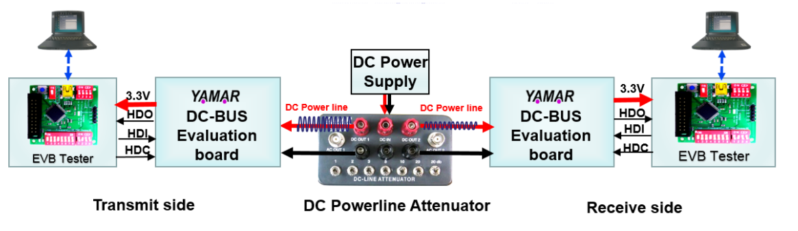
Figure 7 - DC-BUS Test setup

Figure 8 – BER Vs SNR of SIG device @19.2Kbps example
References
- ISO 17987-8 DC-LIN - “Road vehicles — Local Interconnect Network (LIN) — Part 8: Electrical physical layer (EPL) specification: LIN over DC powerline (DC-LIN)”
- CISPR 25 – International standard https://webstore.iec.ch/publication/61522
- SIG100 Data sheet- https://yamar.com/product/sig100/
- “On the global EMC aspect of broadband powerline communications using the "HF" frequency band” – H. Widmer - 2000 International Zurich Seminar on Broadband Communications. Accessing, Transmission, Networking. Proceedings.
- “PLC systems for electric vehicles and Smart Grid applications” – S. Barmada et.el. - 2013 IEEE 17th International Symposium on Power Line Communications and Its Applications.


