Redundant LIN-BUS Networks using DC-LIN Powerline Communication
General
The usage of DC-LIN powerline communication (PLC) as redundant data channels for existing LIN-BUS networks in today's and future vehicle platforms, without increasing the vehicle harness is described hereby.
Furthermore, DC-LIN enables the usage of multiple PLC channels for data redundancy. The availability of many PLC data channels allows Frequency hopping controlled by the data-link upper layer.
The LIN-BUS is commonly used in the automotive industry for controlling sensors and actuators distributed across the vehicle platform, such as roof, seats, windows, doors, and more.
The increasing demand for additional reliable LIN-BUS networks has a direct effect on the vehicle’s harness size and its reliability.
The DC-LIN technology is already standardized as a new LIN-BUS physical layer - ISO 17987–8.
SIG10x DC-LIN powerline as a redundant LIN-BUS network
Figure 1 depicts an example of existing front lights (LIN A) and windows (LIN B) control networks. The body control module (BCM) consists of LIN A, LIN B Masters and each one of the lights and windows consists of LIN slave modules.
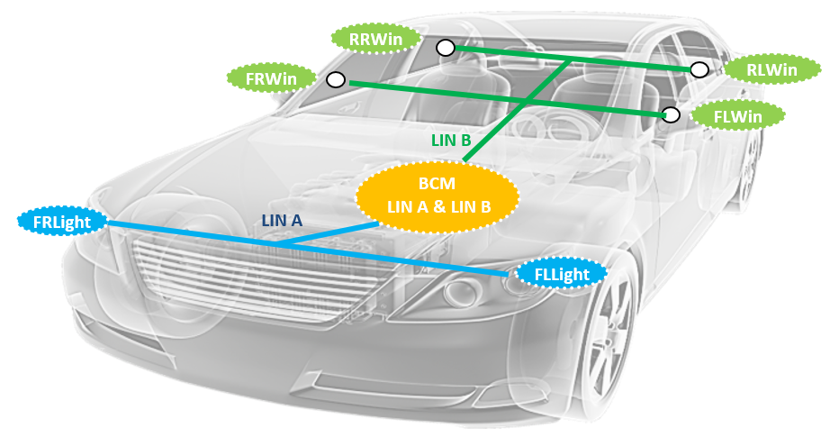
Figure 1– Existing LIN A (lights) and LIN B (windows) networks example
Figure 2 depicts adding two DC-LIN redundant networks to the example in figure 2 using the existing vehicle’s power line. Each DC-LIN network (Lights and Windows) operates on a different carrier frequency (F0 and F1). Figure 3 depicts the DC-LIN PLC network using SIG10x devices. Green presents communication at carrier frequency F0 and Blue represents carrier frequency F1.
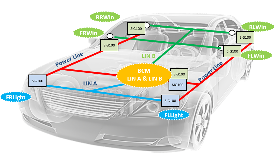
Figure 2 – Redundant power line networks
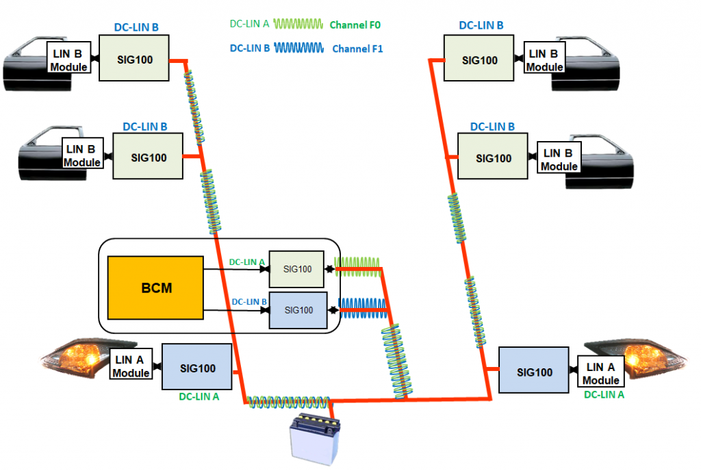
Figure 3 – DC-LIN over power line of LIN A and LIN B networks example
The DC-LIN SIG10x power line transceiver devices
By nature, the vehicle powerline is a noisy communication channel with a frequency response that varies in time and is a highly attenuated data communication environment.
The DC-LIN technology was developed taking in mind the vehicle’s PLC challenges. It fulfills the following requirements:
- Provide uncompromised reliable communication performance.
- Transparent data interface with the existing LIN-BUS network protocol.
- Enable multiple DC-LIN networks using a single powerline, allowing selecting between many carrier frequencies.
- Low power consumption at Sleep mode.
- Meet EMC/EMI regulations.
- Small footprint cost-effective solution.
The DC-LIN technology is implemented in the SIG10x UART/DC-LIN powerline transceiver ICs.
SIG10x operation principle
The SIG10x is a byte-oriented UART/DC-LIN transceiver over the DC powerline (DC-BUS). The device merges both data and power over the powerline, eliminating the need for control and data wires. The devices use a unique multiplex digital signaling technology that overcomes the powerline noisy environment at bitrates up to 115.2Kbit/s.
The SIG10x conducts data over powerline as a half-duplex Master-Slaves network of multiple SIG10x devices. The SIG10x operates at a selectable carrier frequency between 5MHz and 30MHz (100 kHz spacing) allowing multiple independent networks to operate over the same powerline using a different carrier frequency for each network. Two alternate user-pre-defined frequencies allow hopping between these frequencies for redundancy when communication fails on the main frequency.
Since the SIG10x operate as a transceiver, it is the responsibility of the upper communication layers to switch between these three pre-defined frequencies. When the Auto-frequency-change mode enabled, the SIG10x automatically hops between Main, ALT1, or ALT2 configured frequencies when no powerline communication activity detected in more than 2 sec. It indicates that neither transmission nor reception is detected over the powerline on this frequency.
SIG10X communication flow
Figure 4 depicts a typical SIG10x DC-LIN network, demonstrating a single byte transmission from the SIG10x DC-LIN Master device to three SIG10x DC-LIN slave devices. The coupling to the power line is via a capacitor. When the Master SIG10x TX device detects a start bit from its controller in its HDI pin, a powerline PLC-byte transmission starts. At the receiving side, SIG10x slave devices detect the PLC-byte and decode it into the original byte and transfer it to its controller via HDO pin. The latency (Trx_delay) is only ~2.5 bits. There is no restriction to the number of bytes sent.

Figure 4 – SIG10x DC-LIN network example
SIG10x channel parameters
Carrier frequency: 251 selectable frequencies between 5MHz - 30MHz with 100 kHz spacing.
Powerline bitrate: 9.6kbit/s, 10.4bit/s, 19.2Kbit/s, 38.4Kbit/s, 57.6kbit/s, and 115.2kbit/s.
Powerline voltage: Any, with proper powerline coupling interfacing
Cable length: Depends on the powerline AC loads signal attenuation (100m is practical)
Cable type: Any cable.
References
ISO 17987-8:2019 - Road vehicles - Local Interconnect Network (LIN) - Part 8: Electrical physical layer (EPL) specification: LIN over DC powerline (DC-LIN)
SIG102 Data sheet – SIG102 - Multi I/O Control Over DC Powerline Network
Truck Trailer redundancy – Truck-Trailer power line as a redundant CAN channel


